Special thanks goes to Mark Mullins over at ISEMag, and his article entitled Can PoE Take the Heat?.
When Power over Ethernet (PoE) is delivered over twisted-pair copper cabling, the temperature within cables can rise, increasing the potential for insertion loss. Insertion loss is the ratio of the received signal to the amount of inserted signal power at the end of a cable. It describes the strength (or loss) of the signal at any given point on your cable, commonly known as cable attenuation. Insertion loss may require administrators to shorten the length of a cable to maintain signal quality.
RULE: the higher the power, the greater the potential for heat.
The potential for heat generation by PoE also multiplies as newer devices with higher power budgets evolve. As Ethernet technology advances and the power and data transmitted from Power Sourcing Equipment (PSE) to more sophisticated Powered Devices (PDs) increases, the more insertion loss can become an issue. This blog will take a closer look at the potential heat concerns when it comes to PoE.
How Does PoE Standard Cabling Function?
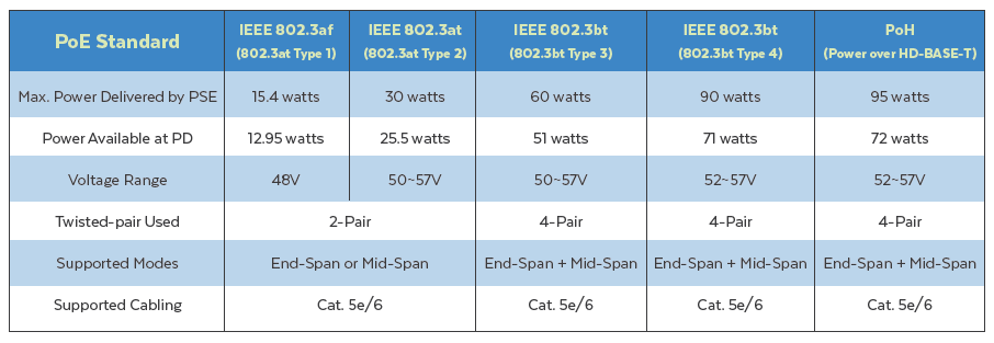
The following chart outlines the distinctions of the 4 Types of PoE standards. It discusses essential differences in how power and data transmit in each of these technologies.
4-Pair PoE and Your Cabling Infrastructure
In the early days of Power over Ethernet (PoE), organizations deployed cables that supported a variety of low powered devices (PD) like VoIP phones and simple security cameras. These networks initially powered devices at budgets per port of 15W and later 30 Watts.
Once PDs grew in sophistication, and the IEEE updated the 802.3at and now 802.3bt standards, a newer era of PDs ushered in. That is where we are today. Devices like high-performance wireless access points, digital displays, PTZ cameras and more, require 60W and are even pushing the demand to 90W per port. As a result, cabling requirements have also had to change from a 2-pair implementation to 4-pair PoE.
As many of you already know, there are currently 4 Types of PoE available. These are the approved IEEE standards with Types 3 and 4 being the most up to date.
How Power and Data Transmit: 2-Pair versus 4-Pair
IEEE 802.3af and 802.3at, PoE Types 1 and 2, deliver power and data in one of two ways: the first way is power and data simultaneously over pairs 1-2 and 3-6, as shown in Illustration one. This technology appears in 10/100BASE-T and 1000BASE-T applications.
Illustration one:
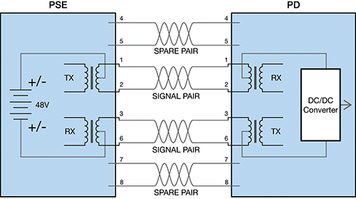
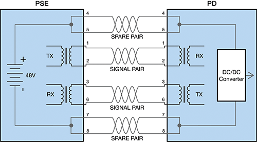
Illustration two, the second way, delivers data over pairs 1-2 and 3-6 while providing power over the spare pairs 4-5 and 7-8 and is compatible only with data signals that use 2 pairs.
Illustration two:
Cabling Requirements for Types 1 and 2
PoE Types 1 and 2 transmit power by applying a common-mode voltage on the 2 pairs. The current splits evenly between the 2 conductors. DC resistance of each conductor (in the pair) is balanced (equal). Any difference is referred to as DC resistance unbalance. Whenever you have too much unbalance, data signals become distorted and can cause bit errors, retransmits and nonfunctioning data links.
Power and Transmission for Types 3 and 4
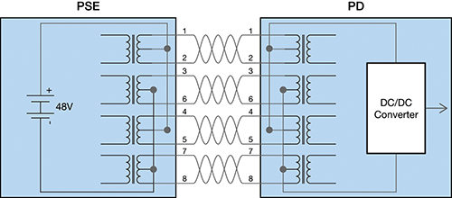
IEEE 802.3bt, Types 3 and 4, deliver power over all 4 pairs simultaneously with data, as seen in illustration three.
Illustration three:
Cabling Requirements for Types 3 and 4
Like Type 1 and Type 2 PoE Illustration One, 4-pair Type 3 and Type 4 PoE also deliver power via common-mode voltage.
DC resistance unbalance also has an effect in IEEE 802.3bt. In Type 3 and Type 4, it is no longer just the unbalance on each pair to consider. DC resistance unbalance between multiple pairs can disrupt data transmission and cause PoE to stop working.
- Lower quality cables may have variations in the diameter and shape of the conductor, running the risk of DC resistance unbalance.
- Inconsistent termination can also cause DC resistance unbalance.
While a DC resistance unbalance may exist on a vendor’s cable, field testing can ensure there’s no DC resistance unbalance performance after installation.
Advanced field test sets can quickly and easily test DC resistance unbalance within a pair and between pairs. You can know your cable plant will perform in 2 and 4-pair PoE applications.
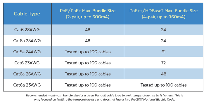
Cable Guidance from TIA on Temperature Rise [TSB-184-A]
Telecommunications Industry Association (TIA) TSB-184-A guides cable installation for PoE, PoE+, and PoE++. The PoE++ standard (60 W) transmits up to 960 milliamps (mA), over 4 pairs. That said, TSB-184-A recommends that the temperatures of a cable not exceed 15℃ within the center of the bundle.
The factors that contribute to temperature rise are:
- Bundle size
- Current running through the wire pairs in relation to the number of pairs energized
- Gauge and construction of cable wire
The ITIA published ANSI/TIA-568.2-D formally recognizes 28 AWG patch cords as being standards-compliant and safe for all PoE standards, provided the bundle size is smaller.
IEEE 802.3bt Uses A Constant Power Delivery Model
PoE technology, by nature, uses ‘constant power.’ A constant power model limits powered devices to a maximum wattage, regardless of the cable length. The implication is that shorter channels deliver less power and current from the source (due to lower power losses over the channel) than in earlier PoE Types, which use constant current models.
The result of constant power delivery is that you have a lower temperature rise. That means PoE cable bundles can be larger than current standards recommend. Experts agree that this recently proven constant power methodology can become the new best practice for cable implementation. Whether this becomes official has yet to be determined.
Underwriters Laboratory LP Certification
Underwriter’s Laboratories (UL) has a Limited Power (LP) Certification to help simplify cable choice for PoE applications. The LP Certification, not a listing or rating like plenum or riser ratings, indicates cable testing for PoE under worst-case installation scenarios without exceeding the temperature rating of the cable.
The LP Certification parameters include bundle size, ambient temperature, and the environmental effects of enclosed spaces or conduits.
When power requirements are 60W (Type 3) or greater, the NEC includes ampacity tables. They specify the maximum ampacity allowed for:
- Cable bundle size
- Conductor gauge
- Cable temperature rating installed in an ambient temperature of 30°C (86°F)
These tables address heat rise to help with choosing the right grade of cable.
When you’re still not sure of the potential for heat in a PoE installation, the simplest solution is to reduce the number of cables per bundle.