Unless you are working on a science project for MIT or you are a DIY build it yourself nerd, you will probably not in your life build a switch. However, it can be helpful to understand the fundamentals of how this works.
The Power over Ethernet (PoE) 802.3bt standard is the third and most recent adaptation to the IEEE standard that specifies low voltage power transfer to networked devices.
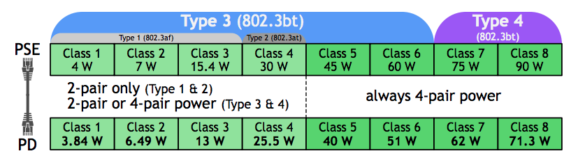
Image Source: Ethernet Alliance
Type 3 PoE delivers up to 60W from the Power Servicing Equipment (PSE) for up to 51W of input power at the Powered Device (PD). Type 4 PoE delivers 90W from the PSE for up to 73W of input power at the PD. Both versions utilize all four of the twisted-pair copper wires inside a Cat5e, Cat6, or Cat6a Ethernet cable.
Tools You Need To Get Started
Any powered device will need basic Integrated Circuit (IC) materials. These include a board, a soldering iron, a converter, diodes, wire to connect, and other components that curl the hair of most of us when we contemplate the complexity of what is ahead.
Forget the sequence that the signal will need to travel down; the sheer size of ICs inside the PD requires magnification and a steady hand to attach diodes and other components.
Since most of the people reading this blog aren’t able to construct one of these devices themselves, it makes more sense to focus on the functioning within the different parts inside the switch (also known as PSE) supporting that function.
Power Up
To start your powered device, you need to connect it to a switch to “turn on” the power. Generally, manufacturers also include a light to let end-users know power is being supplied.
The PSE (switch) communicates with the PD in a series of back and forth signals.
The initial pulse that comes from the PSE to the powered device, also known as the handshake, is between 1 and 2 volts. Ultimately, the 802.3bt will need the following to operate:
Type 3: 40-51 Watts
Type 4: 62-71.3 Watts
What happens during the interconnection is that the PoE-PD controller and the DC/DC converter “connect.” Next to those power connections is a third control signal used to keep the DC/DC converter off when the PoE-PD controller is in the process of charging the input capacitance.
How the capacitor works
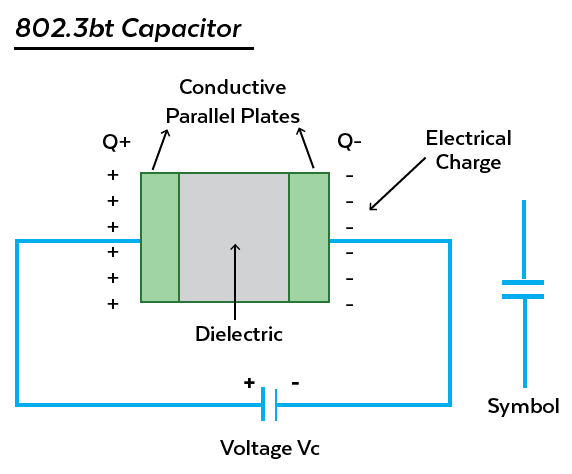
What capacitance refers to is the potential amount of charge that a capacitor stores. The larger the plate inside the capacitor, the higher the capacitance, or the larger the charge that is stored.
A capacitance on an 802.3bt looks something like this and more than likely appears in a series to support the back and forth pulsing that lets the PSE know how much power to send to the PD. This prevents damage to the PD due to too much power.
Type 3 requires 3-4 pulses.
Type 4 requires 5 pulses.
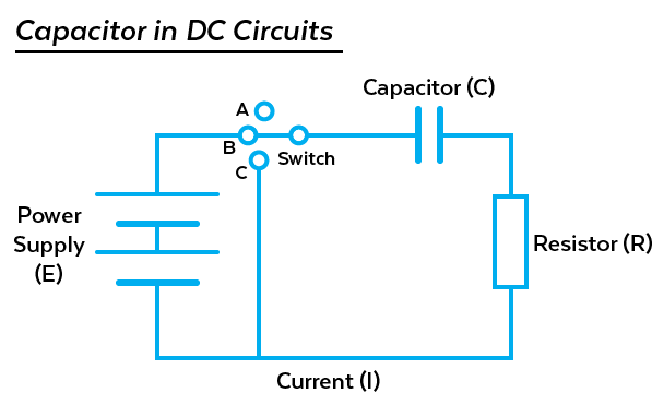
The diagram below illustrates the capacitor in relation to the other functioning parts of the switch (i.e. the power supply, switch, resistor, and the signal path).
Once the correct level of power from the PSE reaches the PD, the PD turns on. The LED power indicator light should be on.
Type 3: 40-51 Watts
Type 4: 62-71.3 Watts
The Signal Path Passes The Start Function And Supplies Power To The Powered Device
At this point, the power moves through the powered device, and resistors begin to delimit the electrical current. As its name suggests, a resistor is a component that resists the flow of electrical current. There are a variety of resistors deployed throughout a board within the PD.
Resistors perform several functions. Resistors help:
- Reduce current flow
- Adjust signal levels
- Divide voltages and bias active elements
- Terminate transmission lines
- Generate heat
- Match and load circuits
- Control gain
- Fix time constants
Resistors with resistance values over a range of more than nine orders of magnitude are commercially available.
For a detailed overview of powered device design, Tony Morgan, Senior Applications Engineer with Silver Telecom has written an informative article.
More About the PoE Switch (PSE)
PoE switches are an integral part of PoE technology. These PSE devices have built-in Ethernet functionality that enables you to power your PDs using network cables.
There are several different types of PoE network switches on the market, such as 8, 12, 24, and 48 port versions. PoE switches are either unmanaged or managed. Simply put, an unmanaged switch is a plug-and-play device, which means that literally, all you have to do is plug it into work. A managed switch allows for greater control over how data travels over the network and who has access to it.
Why You Need a PoE Switch
There are many benefits to a PoE switch. PoE switches are:
- Flexible. PoE switches do not have the restrictions of non-PoE switches that often need additional PSEs and extension cables.
- Simple. There is no need for additional PSEs and installation locations. Quality PoE switches embed the Simple Network Management Protocol (SNMP), which provides a straightforward way to supervise and manage the switch.
- Cost-Effective. Because a PoE network switch needs no additional electrical wire and outlets, there are significant savings on installation and maintenance costs.
Conclusion
For most of us, it is a whole lot easier to leave this gadgetry to the professionals.
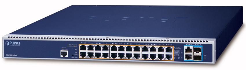
Our GS-6322-24P4X is a managed 802.3bt PoE ++ Switch with dual modular power supply slots that promote power management efficiency and flexibility in large-scale networks.
Here are some features:
- Ports: 24 10/100/1000TX + 2 10G SFP+ with 1 console port
- Type: Managed
- PoE Ports: 24
- Standards: 802.3bt PoE++ PSE (Type 4)
- PoE Budget: 2280W
- Power Consumption: 2032W/6933 BTU (singe PSU), 2377W/81411 BTU (dual PSE)
- Throughput: 95.3 Mpps@64Bytes
- Operating Temperature: 0 to 50°C
- TAA Compliant
Learn more about our PoE and Gigabit Technology Switches.